Hydraulic Brakes Adjustment Guide
With a brand new ebike, a small amount of brake rubbing and noise can occur during a break-in period known as bedding-in new brakes. Rubbing and noise will often resolve over time with normal brake use (after about 40-80km). Ebike brakes and components may wear out faster than would be the case for non-motorized bicycles, requiring more service. If you are experiencing brake noise after the break-in period (25-50 miles), follow the steps in this article to adjust the brakes.
The hydraulic brake adjustment will involve:
- Checking the wheel to make sure it is fully seated in the frame dropouts. An improperly seated wheel can cause the brake rotor on the wheel to rub on the brake pads and cause noise.
- Checking that the brake rotor is true (straight) and in good condition. A damaged or dirty brake rotor can lead to reduced brake performance or noise.
- Centering the brake caliper by adjusting the positioning so the brake pads are centered and parallel to the brake rotor. A brake pad or brake caliper that is not properly positioned can lead to reduced brake performance or noise.
- Adjusting the brake lever reach. Make sure the brake lever is adjusted to a position that is comfortable for you.
These instructions only apply to KG4 with hydraulic brakes
Tools Needed:
- 2mm Allen wrench
- 4mm Allen wrench
- 5mm Allen wrench
- Torque wrench
- 18mm wrench
Check the Position of the Wheel
- Get the ebike ready for maintenance. Turn off the bike, remove the battery, and press and hold the power button to discharge any remaining power.
- Identify which brake needs to be adjusted.
- Check that the wheel is fully seated in the dropouts and, centered with the bike. A loose wheel, or one that is not centered in the fork dropouts, can cause brake noise when the brake rotor rubs on the brake pads as the wheel spins. If the wheel is not fully seated in the dropouts or centered with the bike, follow the steps below to adjust the wheel.
- Adjust the front wheel:
- Use an 18 mm wrench to loosen (but not remove) the axle nuts on both sides of the wheel.
- Turn the thumbnut on the other side to create more space for the fork dropouts.
- Reposition the wheel so the axle is in line with the fork dropouts. Ensure the wheel is centered, and carefully lower the bike onto the wheel axle.
- Adjust the wheel carefully so the axle is level and fully seated in the dropouts.
- Use an 18 mm wrench to tighten the axle nuts. Torque both axle nuts
- Adjust the rear wheel:
- Use an 18 mm wrench to loosen (but not remove) the axle nuts on both sides of the wheel.
- Adjust the wheel carefully so the axle is level and fully seated in the dropouts.
- Use an 18 mm wrench to tighten the axle nuts. Torque both axle nuts
- Adjust the front wheel:
Once the wheel is fully seated in the dropouts and centered, continue to the next section to check the condition of the brake rotor.
Check the Condition of the Brake Rotor
- Position the ebike so you can easily see the brake rotor in between the brake pads.
- Spin the wheel to check if it spins freely. There must be little to no contact between the brake pads and brake rotor.
- While the wheel spins, check the condition of the brake rotor. If the brake rotor wobbles at the brake caliper or is damaged, it may need to be replaced.
- Use the brake lever to stop the wheel.
- Squeeze the right brake lever if testing the front brake, and left brake lever if testing the rear brake.(UK only)
- Squeeze the left brake lever if testing the front brake, and right brake lever if testing the rear brake.(EU only)
- While the wheel spins, check the condition of the brake rotor. If the brake rotor wobbles at the brake caliper or is damaged, it may need to be replaced.
Once you have confirmed that the brake rotor is in good condition, continue to the next section to center the brake caliper.
Center the Brake Caliper
- Loosen the caliper bolts. Use a 5 mm Allen wrench to loosen both caliper bolts one turn at a time until the caliper can move from side to side.
- With one hand, squeeze the lever of the brake you’re adjusting. This will move the caliper so the brake pads are aligned with the rotor.
- Push the caliper left or right until it is centered over the rotor.
- Tighten caliper bolts. While still squeezing the brake lever, re-tighten the caliper bolts until the caliper no longer moves side to side.
- Inspect the caliper alignment. Release the brake lever and inspect the caliper alignment. Spin the wheel to test whether the brake pads rub against the disc brake rotor, and check that both brake pads are parallel to the disc brake rotor
- If your brake pads rub the rotor after aligning the caliper, slowly loosen one bolt at a time in quarter-turn increments and repeat the previous steps until the brake pads no longer rub.
- Once the calipers are positioned correctly so that the brake pads are parallel with the rotor and the wheel can spin freely between the pads, torque both caliper bolts to the required 7 Nm.
Once the brake caliper is centered, continue to the next section to adjust the brake cable reach.
Adjust the Brake Lever Reach
Once the brake caliper is centered, adjust the brake lever reach to the user’s preference. Use a 2 mm Allen wrench to turn the small screw on the inside of the brake lever in a counter-clockwise motion to tighten the lever. The brake lever reach must be comfortable for your hand size, but not so tight that there is no space between the lever and handlebar grip.
Brake Pad Replacement
Tools Needed:
- 3 mm Allen wrench
- Remove circlip 38 and unscrew pad fastening pin 39, using a 3 mm Allen wrench.
- Replace new pads 40
- Assemble fastening pin 39 using a 3 mm Allen wrench tightening to a torque of 2 Nm 5%, then refit circlip 38.
Note:
- In a case where pistons are coming out from it’s original position, dis-assemble the caliper to push them back evenly (be careful not to twist the pistons) with a piston press tool.
- Using tools other than a professional piston press tool may cause damage to the pistons and lead to incorrect function.
- If want to perform a bleeding process to the piston or brake lever, please use Elite/Pro JAGWIRE bleed kit and Use RIDEREVER or Finish Line™ Mineral Oil only.
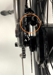
Power Cut-Off Sensor Maintenance
If an Error 25 occurs or the power cuts off without the brake having been pressed, you can adjust the cut off sensor by following the following steps:
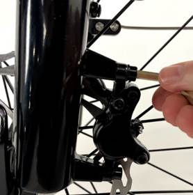
- Use the 1.5 mm Allen key to loosen the screw
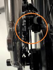
- Move the cut off sensor holder according to the direction as shown
- After confirming the position, use 1.5 mm Allen key to tight the screw (recommended torque 0.35 Nm)